Saturday 23 March 2024

Taranis Q X7 Buddy Box Setup

How to connect two FrSKY TaranisQ X7 radios for shared Instructor and Student control

The Instructor and Student radios are connected via the DSC sockets using a 3.5mm stereo audio cable (TRS style) 

Link to 3.5mm TRS cable


Note that RadioMaster radios require different cables. 3.5mm TRRS (Smart phone style) for "Old" radio and TS for "New" radios. Link to RadioMaster Trainer Cable information


FrSKY TaranisQ X7 trainer setup

Instructor radio (Master)

In the Model Setup page - Set Trainer Mode to Master/Jack

Mixer page (Adjust weights and expo as required. Best to be the same as in the Student radio)

Ch1 100 Ail E30

Ch2 100 Ele E30

Ch3 100 Thr

Ch4 100 Rud

In Special Functions page - Select a switch, Select TRAINER and STICKS and tick box

Bind Instructor radio to the receiver

In Radio Setup  > TRAINER page

Ail := 100 CH1

Ele := 100 CH2

Thr := 100 CH3

Rud := 100 CH4


Student Radio (Slave)

In the Model Setup page

Turn the Internal RF module OFF

Set Trainer to Slave/Jack

Ch Range 1 to 8 (just has to be more than 4)

Mixer Page (Adjust weights and expo as required)

Ch1 100 Ail E30

Ch2 100 Ele E30

Ch3 100 Thr

Ch4 100 Rud


Check direction of throws on both radios and adjust or invert channels as required


Thursday 14 March 2024

Best Radios for INAV 2024


INAV only requires a very simple model setup in the radio, just the 4 control channels plus a few mode switches. 

You can get by with just about any radio system including RadioMaster, FrSKY, FlySKY, Futaba and Spektrum as long as the receiver can output a serial signal using a protocol like iBUS, SRXL2, SBUS or CRSF.

My preference is for radios that use the EdgeTX operating system and ExpressLRS RF protocol. EdgeTX is the most flexible and programmable operating system and ExpressLRS gives the most secure and long range RF link.

Spektrum and FlySKY operating systems are less flexible and more locked down than EdgeTX.

Below are my top suggestions for a good INAV radio in 2024

Note: EdgeTX, INAV and ExpressLRS are all RC Community developed OpenSource projects so they are often updated and  will require a little more research and experimentation to master than traditional locked down systems like Spektrum.


ExpressLRS Radios

1. RadioMaster Boxer ELRS  (or Boxer 4in1 with ELRS RF Module) 

The Boxer is a very reasonably priced radio with plenty of switches. One momentary, one locking, two 2 position, two 3 position and one 6 position switch as well as two pots. It has a full sized JR RF module bay. The only things missing are sliders on the sides. There is a large battery bay for 2S LiPos.

2. Zorro and TX16S are good options too, although I am not a fan of the colour touch screen version of EdgeTX on the TX16S. 

My daily radio is actually the Zorro 4in1 with Ranger ELRS RF module. The game controller form factor is not to everyone's taste but I like it. It uses 18350 Li Ion batteries which are hard to find and have less capacity. But I like the side sliders for panning cameras and also crow braking on gliders. 

The TX16S would suit someone who wants all the bells and whistles including a large colour touch screen. But I find it unnecessarily big and heavy.

3. FrSKY TaranisQ X7 with external BetaFPV or RadioMaster ELRS RF Module

This is FrSKYs cheapest radio and it was my favourite for many years. I love the rotary selector dial and overall feel.
It only binds with FrSKY ACCESS and D16 receivers unless you add an external ELRS RF module.

ELRS Receivers

Any ELRS receiver can be used with any ELRS radio or module

RadioMaster RP1, RP2, RP3, RP4TD ELRS or any of the PWM receivers with Serial output enabled

BetaFPV - ELRS Nano, Lite, SuperD and Micro PWM or SuperP PWM with Serial output enabled

ELRS gear has amazing range, at least 5km even with the nano receiver versions. Or you can think of it as very secure RF link for short range even with obstacles. The diversity receivers like SuperD and RP4TD extend the link security even further for extended long range or close range penetration.


SBUS Radios

1. RadioMaster Boxer 4in1 

All RadioMasters radios come in different versions. CR2500 for one chip multi-protocol (Mainly used for RadioMaster and FrSKY receivers), 4in1 with 4 chip multi-protocol, or ELRS.

2. Zorro and TX16S are also good options. ELRS external module can be added


3. FrSKY TaranisQ X7 (only compatible with FrSKY ACCESS and D16 receivers)

4. FrSKY Tandem and Twin radios (Higher quality hardware but more expensive and limited to FrSKY receivers)


SBUS Receivers

FrSKY X6R, RX6R

RadioMaster R81, R86C

FlySKY iA6B using iBUS or SBUS


My YouTube Playlists to help with the learning curve. It's worth the little extra effort of watching a few videos on the relevant subjects

RADIOMASTER Playlist

INAV Playlist

ExpressLRS Playlist

OpenTX / EdgeTX Playlist

Sunday 14 January 2024

ExpressLRS for Planes

ExpressLRS is an Open Source RF system with amazing long range and low latency. Flight distances of more than 10km are easily achievable using basic ELRS gear and low power transmission.

It was originally designed to work with multi rotors and flight control boards and uses the CRSF serial receiver protocol.


More recently PWM receivers have been released which allow normal servo connection direct to the
receiver without using an FCB. This makes ELRS a viable system for normal line-of-sight planes and gliders.

However it is essential to understand that ELRS is quite different to the traditional RF protocols like FrSKY ACCST / ACCESS or Spectrum DSMX. To achieve the low latency and solid connection over long range the ELRS devs have optimised the data packets to be as short as possible and included safety checks. 

Below are some of the compromises required for ELRS to function properly

Setup selections are made using the ELRS Lua script on your radio, and some of the default options must be changed for fixed wing models.

Channel resolution

To keep data packages small only the essential data is sent with every packet. This means with some Packet Rates not all channels are full resolution.

In the ultra low latency modes Ch 1 to 4 are full resolution, while Ch 5 is only 1 bit (low or high) and all other channels act like 6 position switches.

However more recently, lower frequency Packet Rates have been added, which do give full resolution on all channels and are recommended for fixed wing use. 

Best settings for fixed wing models are:

Packet Rates 100 Full or 333 Full with Switch mode on WIDE.

However Ch5 should not be used for anything but arming, even though it can be full resolution.

Channel 5 requirement

To function safely ELRS needs to know when the model is armed or flying. So it looks at the data from Ch5, which is sent with every data packet, to check the PWM value.

Ch5 needs to be in the "High" state, or PWM value above 1500ms, to show that the model is armed or flying. 

When Ch5 is high the buttons on your ELRS RF module are locked to avoid accidental mid air changes, which could cause a loss of control. 

Dynamic Power only works when Ch5 is High. Dynamic Power continuously adjusts the RF transmitting power to the minimum required.

So Ch5 should be set as the arming or throttle cut switch or set as high, and not left unassigned or used for control surfaces or throttle. This applies to any model, even if they don't require arming, including motorless gliders.

Here is a great explanation by RC-Soar - https://rc-soar.blogspot.com/2023/08/an-introduction-to-elrs-including.html

ExpressLRS on GitHub - https://www.expresslrs.org/quick-start/getting-started/


Wednesday 11 October 2023

Unusual RC problems and solutions

This post will be an ongoing log of troubleshooting solutions that I come across in video comments and questions. 

Some solutions are obvious and just require reading the manual, or checking connections. But some solutions are unexpected and weird.

This will document some of the more unusual problems that can mess up an RC setup


List of odd problems and the solutions


INAV

"Pitch / Roll not entered" error message

Cause - Switch mistakenly assigned to Aileron channel in the radio

Disarming with any aileron input

Cause - Used an existing model setup in the radio which had aileron mixing on the same channel as Arming in INAV.

GOLDEN RULE - Create a new fresh model for your INAV setup to avoid any leftover mixes


SpeedyBee F405-Wing MINI 

USER modes not available for analog camera switching in INAV 7.0

Cause - This feature missed the deadline to be included in INAV 7.0. Updated firmware available on the Product page and INAV 7.1

Board stopped working after prolonged setup session

Cause - Bent pin on the "between-board" connector after repeated disassemblies.


SpeedyBee F405-Wing 

No voltage on DJI 9V port 

Cause - Bent ground pin needed straightening

No output on S8, no Soft Serial for S-Port function 

Cause - Factory firmware bugs, upgrade to INAV 6.1.1


FrSKY GRX8 

Receiver unable to enter bind mode 

Cause - Worn bind button contact. Needed to push harder on the bind button


Kootai A505 J3 Cub 

Will not initiate 

Cause - Futaba FASST protocol uses REVERSED throttle channel


Skywalker X8 

Wings out of alignment. 

Manufacturer glued the spar at the top of the channel in one wing and bottom of the channel in the other wing - Cut out spar and foam packing and re glue correctly.


FIMI Manta - Matek F405 VTOL - Ardupilot ELRS 

RC connection won't work 

Cause - SERIAL5 was set to CRSF (Parameter = 23) as well as SERIAL6 which prevented Rx connection.

Only SERIAL6 should be set to CRSF


Tuesday 12 September 2023

ArduPilot - QGroundControl for Mac

ArduPilot configuration using QGroundControl for Mac on a simple GPS enabled FPV wing. No ground station, no compass, no airspeed sensor.


Mission Planner is the most popular ArduPilot configuration program but there is no Mac version

My gear for this ArduPilot test:

Matek F405-Wing board, LTE Rambler Wing, RadioMaster Boxer, ELRS receiver and RF module.


QGroundControl for Mac

Download and install QGroundControl for Mac


ArduPilot firmware
Go to the ArduPilot Github repository and find the latest stable ArduPilot Plane firmware for Matek F405-Wing (or your FC). Download the hex file that includes the boot loader (arduplane_with_bl.hex)

Firmware page - https://firmware.ardupilot.org/Plane/


All of this information comes from the ArduPilot Plane documentation - https://ardupilot.org/plane/index.html


Initial firmware flashing with INAV

QGroundControl cannot be used to flash Ardupilot to a board that does not already have Ardupilot loaded. INAV or BetaFlight can be used for this.

Connect the board to INAV Configurator in DFU mode by holding the DFU button while connecting the USB

Select Firmware Flasher then Load Firmware (Local)

Locate the dowloaded arduplane_with_bl.hex file and select Flash Firmware

Once Ardupilot firmware is flashed to the board QGroundControl can be used for updates and configuring.


Configuration with QGroundControl

Open QGroundControl and connect the F405-Wing via USB

IMPORTANT: First step is to RELOAD the firmware using QGroundControl now that Ardupilot is on the board. 
Click on Firmware, unplug the board, then reconnect to start the upload.

This seems to be necessary to make the sensor calibration and servo outputs behave correctly, not sure why.


Once the firmware has been updated and the board rebooted, the Horizon icon should react to board movements, and sensor setup notices will pop up.


Click on the Q icon (top left) to open Tools, then Vehicle Setup

Parameters screen should appear in a few seconds.


Calibrate Accelerometer

Click on the Sensors tab (left of parameter screen) and select Accelerometer

Follow the prompts to calibrate the accelerometer while holding the board in all 6 orientations.


Set up the ArduPilot model in your radio.

It is important to create a fresh model in your radio to avoid any leftover inputs, mixes or overrides.

Model setup for ArduPilot must have no mixing, no rates or expo. No matter what style of plane you are configuring, this is how the mixing page on your radio should be. 

All control surface mixing and channel reversing is done in QGroundControl


Ch 1 100% AIL

Ch 2 100% ELE

Ch 3 100% THR

Ch 4 100% RUD

Ch 5 100% MAX (ELRS requirement)


All ArduPilot's Flight Modes are on Ch 8 by default

Ch 8 100% SC for 3 positions operating 3 Modes

OR

Mixing for 6 modes using combination of SC (3 pos) and SD (2 pos) switches

Ch 8  31% SC -45% Offset, SD Up

ADD  31% SC +45% Offset, SD Down

OR

Ch 8  65% S3 (6 position switch) 

Weight of 65% is required so the 6 PWM values match the ArduPilot Mode PWM ranges

Make sure the receiver is bound to the radio 


Parameter Setup

To find and edit items in the Full Parameter list, click on Parameters then type in the search field, then click on the relevant line to bring up the Parameter Editor box.

The firmware does not correctly preset all of the parameters for the F405-Wing board. The following changes are essential to configure the board for successful operation.

Configuring SERIAL inputs (UARTS)

Note that some FCBs have a different UART numbering sequence to the Ardupilot SERIAL numbering. Check the board's product page or the Ardupilot board info list. https://ardupilot.org/plane/docs/common-autopilots.html

Luckily the Matek F405-Wing board UARTs do match.

The following SERIAL parameters need to be entered

1. Receiver protocol and UART1 selection

SERIAL1_PROTOCOL - Manually enter "23" 
This changes the RC protocol to RCIN - ELRS/CRSF
This info is on the Matek product page and ELRS documentation

2. GPS connects to UART3 and/or UART4

SERIAL3_PROTOCOL - GPS

Baud Rate is automatically adjusted

No other SERIAL inputs need to be changed at this stage (Unless you have HD FPV that needs UART connection)

Connect ELRS receiver RX and TX to UART1 on the board. Connect receiver power to 4.5V pin if you want it to be powered from USB for setup


Calibrate Radio in QGroundControl

With the receiver connected and bound to the radio, click on the Radio tab.

Follow the prompts while moving sticks and switches to calibrate Ardupilot for the radio. 

This configures the stick functions or RC inputs, and sets the channel endpoints


Configuring motor and servo connections

SERVOn_FUNCTION


Edit SERVO Parameters to be as shown below

SERVO1_FUNCTION - Throttle

  Change SERVO1_MIN to 1000

ESC signal connects to S1 pins on the F405


SERVO3_FUNCTION - ElevonLeft 
May need to change and/or reverse later

  Change SERVO3_TRIM to 1500

Left Elevon connects to S3 pins on the F405


SERVO4_FUNCTION - ElevonRight 
May need to change and/or reverse later

Right Elevon connects to S4 pins on the F405


Configuring other parameters

SAFETY (Click the Safety tab)

Safety Checks - Leave ALL ticked.

Return To Launch Altitude - Change if desired. I use 7000cm (70m)


COMPASS_ENABLE - Disable 

Otherwise Safety Checks will prevent arming


ARSPD_TYPE - None 

Otherwise Safety Checks will prevent arming


ARMING_RUDDER - ArmorDisarm 

To allow arm and disarm with rudder stick. 

Arming by a Switch is also available


FS_LONG_ACTN - RTL 

Return to Launch on a "longer than short" Failsafe. 

Short Failsafe Action is preset to CIRCLE to attempt RC reconnection, then reverts to Long failsafe after 2 sec.


SERVO_AUTO_TRIM - Enable 

Continuously trim servo midpoints for level flight in Manual


TRIM_PITCH_CD - 300 

300 centi degrees for 3º of nose up for level flight (maintain altitude) in FBWA. Adjust for your craft


TRIM_THROTTLE - 38 

For criuse throttle of 38%. Adjust for your craft


RSSI_TYPE - ReveiverProtocol 

Allows ELRS RSSI and LQ to be displayed correctly


Configuring Control surface movements

1. Correct stabilisation directions

IMPORTANT - Do this before step 2.

Check control surface movements for stabilisation in FBWA Mode

Without touching the sticks - 

Left elevon should move up and right elevon down, when the left wing is raised

Right elevon should move up and left elevon down, when the right wing is raised

Both elevons should move up when the tail is raised

I needed to make the following changes to give correct stabilisation elevon movements

SERVO3_FUNCTION - Change to ElevonRight

SERVO3_REVERSE - Change to Reverse

SERVO4_FUNCTION - Change to ElevonLeft


2. Correct stick input directions

Check control surface movement for stick inputs in Manual Mode

My elevator action was reversed, so I needed reverse the elevator input (RC2) in parameters 

RC2_REVERSED - Reverse

Coming from INAV I prefer to reverse RC inputs in QGroundControl and not in the radio. But I think either method is OK in Ardupilot.


Analog OSD Setup

Connect camera and video transmitter to the board


Search for OSD parameters

OSD_ENABLED - Enabled (To turn OSD on)

By editing the OSD parameters you can Enable and Disable OSD elements and position them by changing the X and Y parameters.

There are about 23 horizontal and 13 vertical positions

The F405-Wing board does not have enough memory to include alternative fonts. 

However other fonts can be stored on the SD card and called up using the OSD1_FONT parameter

Download fonts from the Ardupilot Font repository

I changed to the INAV style font (font2.bin) 

Copy the font2.bin file onto the SD card and choose OSD1_FONT = 2


Setup and maiden videos - https://www.youtube.com/@AndrewNewton/search?query=Ardupilot


Thursday 10 August 2023

CC2500 Multi-protocol list


Some of the smaller RadioMaster multi-protocol transmitters are only available with the CC2500 RF chip and not the full 4-in-1 RF chip.

This is fine if you use FrSKY receivers, but you will need a 4-in-1 radio for FlySKY and Spectrum receivers, and all the odd RTF model protocols like V761 etc .

Of course you can add a 4-in-1 external RF module to a CC2500 or ELRS radio for full multi-protocol compatibility


CC2500 RF chip supported protocols 

FrSKY (but not ACCESS, TD or Twin)

S-FHSS (Futaba)

RadioLink

Graupner HoTT 

Skyartec

Full list on GITHUB


4-in-1 RF chip 

Includes all the CC2500 protocols and many more, like Flysky (but not ANT) and Spektrum DSMX

Visit the Multi protocol page for the full list


ELRS 2.4 RF chip

Only compatible with ELRS 2.4 CRSF protocol receivers


Sunday 25 June 2023

Simplified INAV

How to simplify INAV model setup and start flying sooner.

The key to simplicity is having a plane that is trimmed and balanced well mechanically, and not starting with the confusing AUTO modes. With INAV 6.1.1 the default tuning PIFFs (stabilisation parameters) will be OK for most normal performance planes.

Auto Launch, Auto Tune, Auto Trim and Missions will greatly complicate your first INAV experience. It is much simper to get the model flying well first then add the fancy stuff later.

This article is intended for fixed wing pilots who know how to mechanically set up a model for correct throws, trims and CG. 

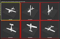
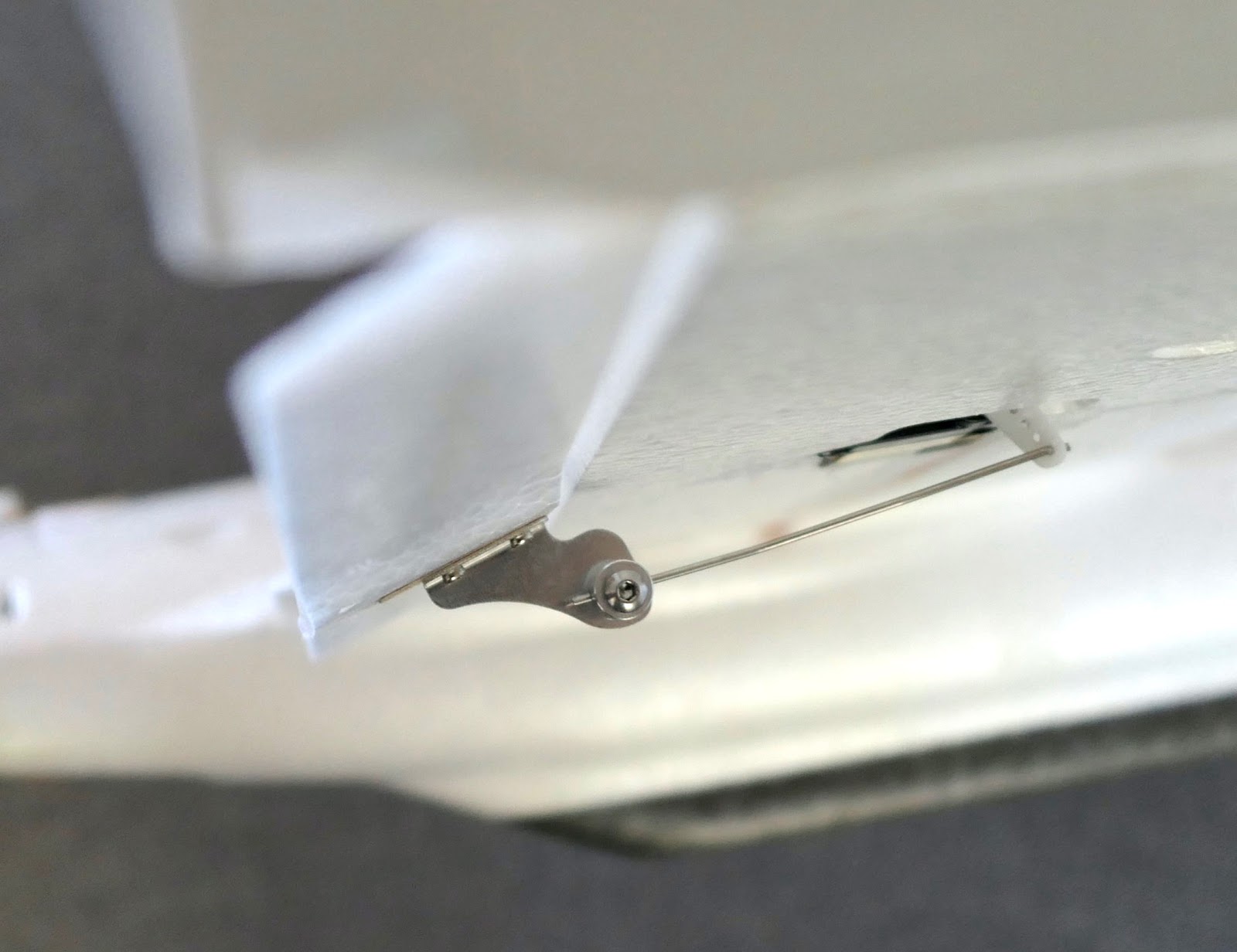
Start with an easy to fly model that has adjustable push rods.

Important first step 

Before you install the flight control board, adjust the pushrod lengths and connection holes to give reasonable throws. This can be done with a servo checker or using your radio and PWM receiver. 

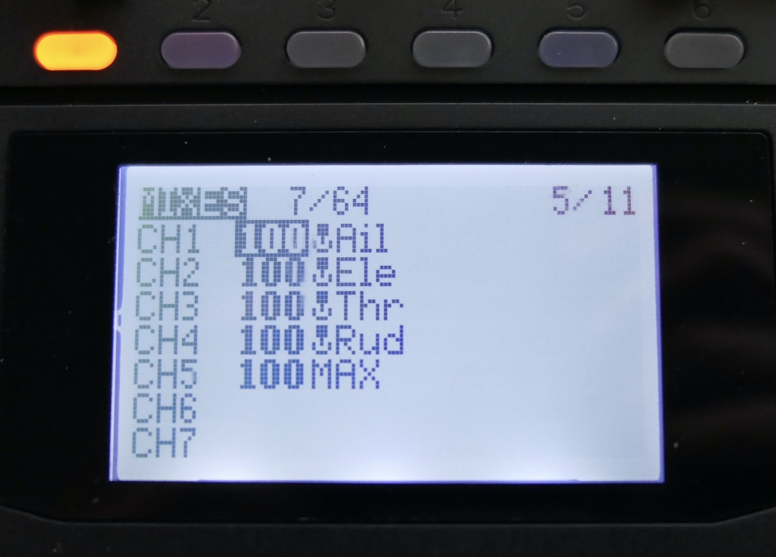
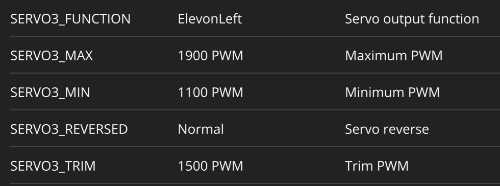
Aim for reasonable throws using 100% servo travel because INAV manual mode uses 100% weight and 30% expo by default

Then fly the model to check aileron and elevator trims and CG placement. To adjust trims you need to land and adjust the pushrod lengths mechanically without touching the radio trims.  

Radio trims should never be used in INAV because they will be ignored in stabilised modes but active in manual mode.

Doesn't have to be perfect and it's OK if the plane is a little too agile with these full throws, as long as it is flyable.

Once the trims are close to correct you can enable "Continuously trim servos" in the Configuration page. This will continuously save fine adjustments to the servo midpoints for level flight in Manual.

Essential INAV Modes

The only modes you need to set up initially are ACRO, RTH, MANUAL and ANGLE 

ACRO is the default INAV mode and is active if no other mode is selected. In ACRO the plane is stabilised against any un-commanded rotations, like a side gust of wind. The model will tend to hold its attitude but respond normally to your stick inputs. ACRO is arguably the best general flying mode.

MANUAL is a mode that has to be selected, it is not the default mode. No mode means ACRO, not Manual. MANUAL is used to check trim and CG balance, and for safety if something is wrong with other modes. Experienced pilots may prefer to fly in MANUAL mode.

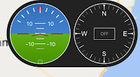
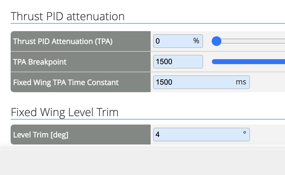
ANGLE is the fully self levelling stabilised mode. It is a mode by itself, but it is also active when any of the nav or GPS modes are used. In this simplified INAV setup it is also used to check board pitch trim. Model airplanes usually need a few degrees of nose-up angle of attack to maintain level flight. This trim setting can be found in the PIDS page - Mechanics Tab - LEVEL TRIM (deg). I usually start with +4 degrees then check if the plane is rising or descending in ANGLE mode and adjust as required.

Flying in ANGLE mode may feel odd to experienced pilots because you have to hold the sticks at the angle you want to fly at and it will self level when you centre the sticks. 

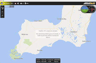
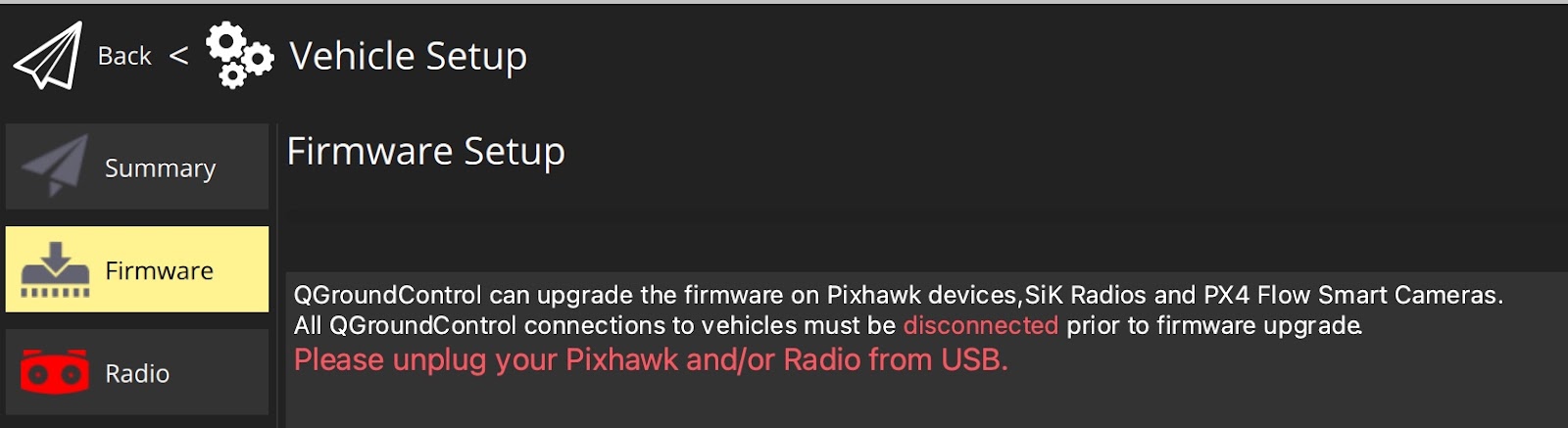
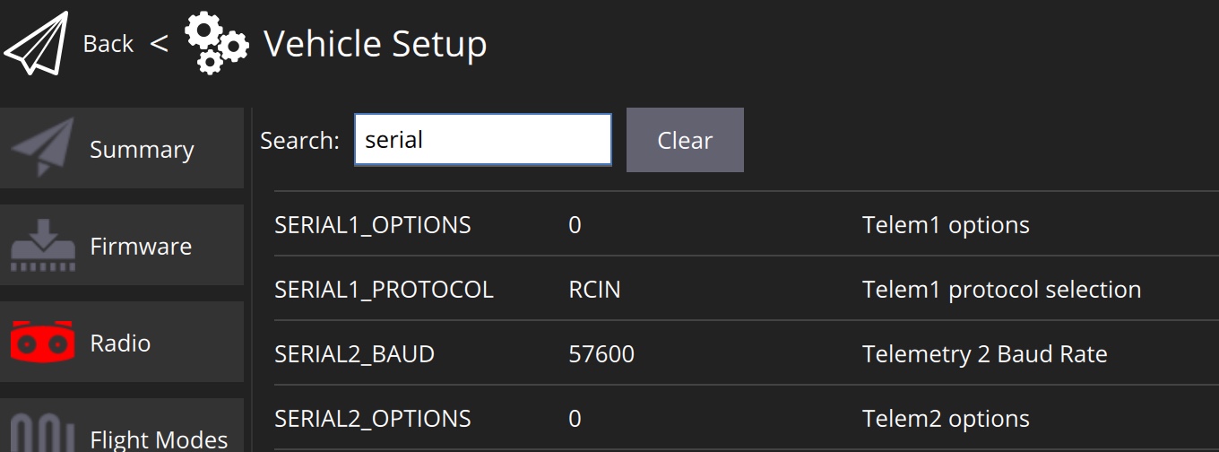
RTH mode uses GPS data to automatically fly the model back to the home location. It can also be set as the Failsafe action, to bring the model back home if RC signal is lost. In the INAV Failsafe screen choose RTH.

The above modes are all you need for a basic setup

Non-essential INAV modes to add once you have a working model

NAV LAUNCH is fun to play with but I prefer to launch normally with full control. It is easy to muck up the switch sequence and cause a failed launch. 

CRUISE and LOITER modes are useful for FPV flights but not essential.

AUTO TUNE / AUTO TRIM are not required if your model is mechanically trimmed with correct CG.

Mode switches

It is best to have your starting switch positions with no modes selected, which means the board will always start in ACRO

Here are my modes for the simple setup

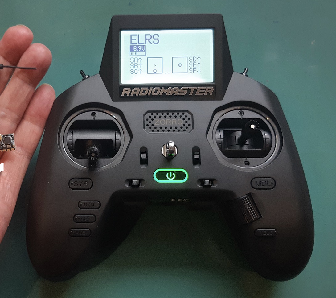
CH 5 (2 position) Nothing - ARM (essential for ELRS receivers)

CH 6 (3 position) Nothing - ANGLE - MANUAL

CH 7 (2 position) Nothing - RTH


Add the fancy modes later

CH 8 (3 position) Nothing - NAV CRUISE - NAV LOITER


Note that when all switches are in the "Nothing" range the board will be in ACRO 


BEFORE THE FIRST FLIGHT

Check the control surfaces are responding correctly to stick movements. Do the High 5 check.

Check the control surfaces are responding correctly for stabilisation. Switch to Angle Mode and check Left wing lifted makes left aileron raise and right aileron go down, tail lifted makes elevator raise.

ACRO Throws

Check the control surface throws in ACRO Mode. They may be too small for sufficient control. Ideally they should be about 80% of the Manual Mode throws. If the throws are too small go to the PID Tuning page and increase the FF parameter for Roll and Pitch, then check throws again. If there is no difference between ACRO and MANUAL Mode throws reduce the FF parameters. 

This will ensure you have enough control to launch in ACRO Mode and some headroom for stabilisation.

First Flight adjustments

On the first flight I will launch in ACRO and fly a few circuits to make sure the plane is flying OK. 


Switch to ANGLE mode. Take note of whether the model holds altitude or climbs or descends. If you haven't entered anything in the Fixed Wing Level Trim window then the plane will most likely descend.

I usually start with +4º and adjust more or less from there.


Launch again, climb to about 50m, fly out a bit then try RTH. Your model should turn and fly back to the arming site and circle above you at about 50m altitude and radius of 75m.

If that all works then you are ready to continue your INAV adventure.